

Creating VLANs
VLANs form the base of your scenario’s network. Each VLAN is an isolated network segment that holds one or more virtual machines.
Adding a VLAN
Section titled “Adding a VLAN”- Find the Networks section in the left sidebar.
- Drag a VLAN onto the canvas.
- A configuration panel opens on the right. Give the VLAN a unique nickname.
- Click Save.
The VLAN appears on the canvas as a container. In the next step you’ll place machines inside it.
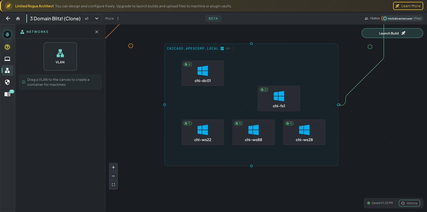 Drag the VLAN tile from the Networks panel on the left onto the canvas. On the right, the CHICAGO.APEXCORP.LOCAL VLAN is a finished domain segment, with a DC, a file server, and workstations grouped in one container.
VLAN Settings
Section titled “VLAN Settings”Rogue Architect handles the network configuration for you, so you don’t need to plan IP schemes, gateways, DHCP pools, or DNS. Give the VLAN a nickname, and the platform fills in sensible defaults for everything else.
To control the networking yourself, turn on Show Advanced Settings at the top of the panel. There you can set your own CIDR, route DNS to a specific DC, and add static host mappings.
Basic Settings
Section titled “Basic Settings”- VLAN Nickname: a unique, descriptive name for this network segment, such as “Corporate LAN”, “DMZ”, or “Attacker Network”.
Advanced Settings
Section titled “Advanced Settings”Turn on Show Advanced Settings to configure the networking details. Any field you leave at its default gets a sensible value from Rogue Architect.
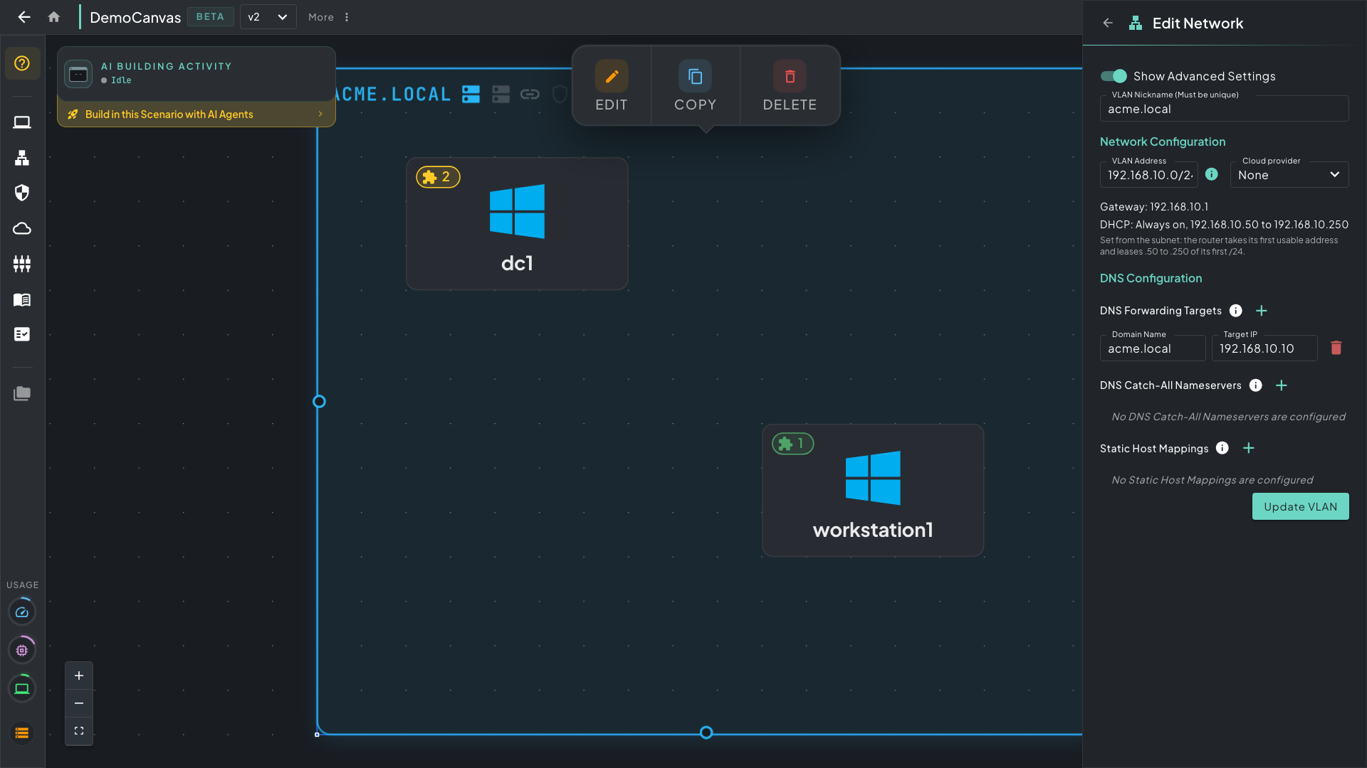 The Edit Network panel with Show Advanced Settings on. The nickname, network address and gateway, DNS forwarding, and static host mappings are all in this one slide-out.
- Network Configuration
- VLAN Address: the network address in CIDR notation, for example
192.168.1.0/24. Use the network address (not a host address) and a/24or larger subnet. - Gateway and DHCP are read-only and follow from the VLAN Address. The panel shows Gateway as the subnet’s first usable IP, and DHCP: Always on with a pool of
.50to.250in the subnet’s first/24.
- VLAN Address: the network address in CIDR notation, for example
- DNS Configuration
- DNS Forwarding Targets: forwards DNS requests for specific domains to the IP addresses you choose. Use it to send domain FQDNs to Domain Controllers or to set up DNS-based C2 channels.
- DNS Catch-All Nameservers: fallback nameservers for DNS queries that don’t match any forwarding target. Use them to send all other lookups to an internal DNS resolver.
- Static Host Mappings: maps specific FQDNs directly to IP addresses. These mappings apply to the whole canvas, not only to this VLAN.
Firewall Rules
Section titled “Firewall Rules”Firewall policies control traffic between VLANs. Click the Firewall icon in the left rail to open the Firewall Configuration panel.
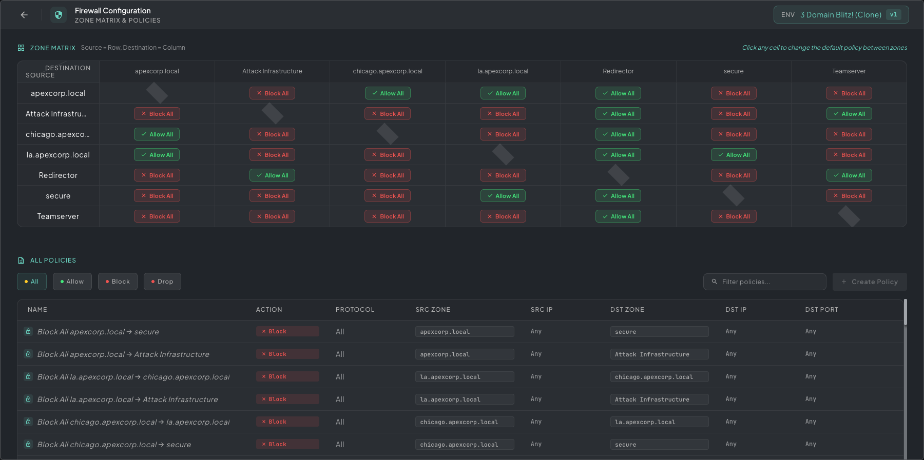 The Firewall Configuration panel. The zone matrix at the top (source rows × destination columns) sets blanket allows and blocks. The policies below it handle specific source, destination, and port rules.
The panel has two sections:
- Zone Matrix: a grid of every VLAN against every other VLAN. Click a cell to switch the default policy for that source and destination between Allow All and Block All. Use the matrix for broad rules such as “Attack Infrastructure can hit anything” or “Secure VLAN is isolated from everything.”
- All Policies: specific rules, listed below the matrix. Click + Create Policy to set the exact source zone or IP, destination zone or IP, protocol, port, and action (Allow, Drop, Deny). Deny rejects the traffic, so the sender’s connection fails at once. Drop discards it silently, so the sender waits until it times out. Block All in the matrix rejects traffic, like Deny. You can filter the list with the action chips at the top.
Policies are evaluated in order. If no individual policy matches, the matrix default applies.
Port Mirroring
Section titled “Port Mirroring”Port mirroring copies the traffic of one or more VLANs to sensor machines. Each destination machine gets an extra, read-only network card that receives a copy of all traffic from the source VLANs. The card has no IP address and sends nothing. Put it in promiscuous mode and listen with an IDS such as Suricata, Snort, or Zeek, capture packets with Wireshark or tcpdump, or feed a SIEM such as Security Onion or Elastic.
- Click Port Mirroring in the left rail.
- Click Add Mirror. The New Mirror form opens.
- Enter a Nickname, such as “IDS sensor tap”.
- In the list on the left, click VLANs to add them as Source VLANs and machines to add them as Port Mirror Destinations. Click an added item again to remove it.
- Click Save.
A mirror needs a nickname, at least one source VLAN, and at least one destination machine. Use the pencil and trash icons on a mirror’s card to edit or delete it.
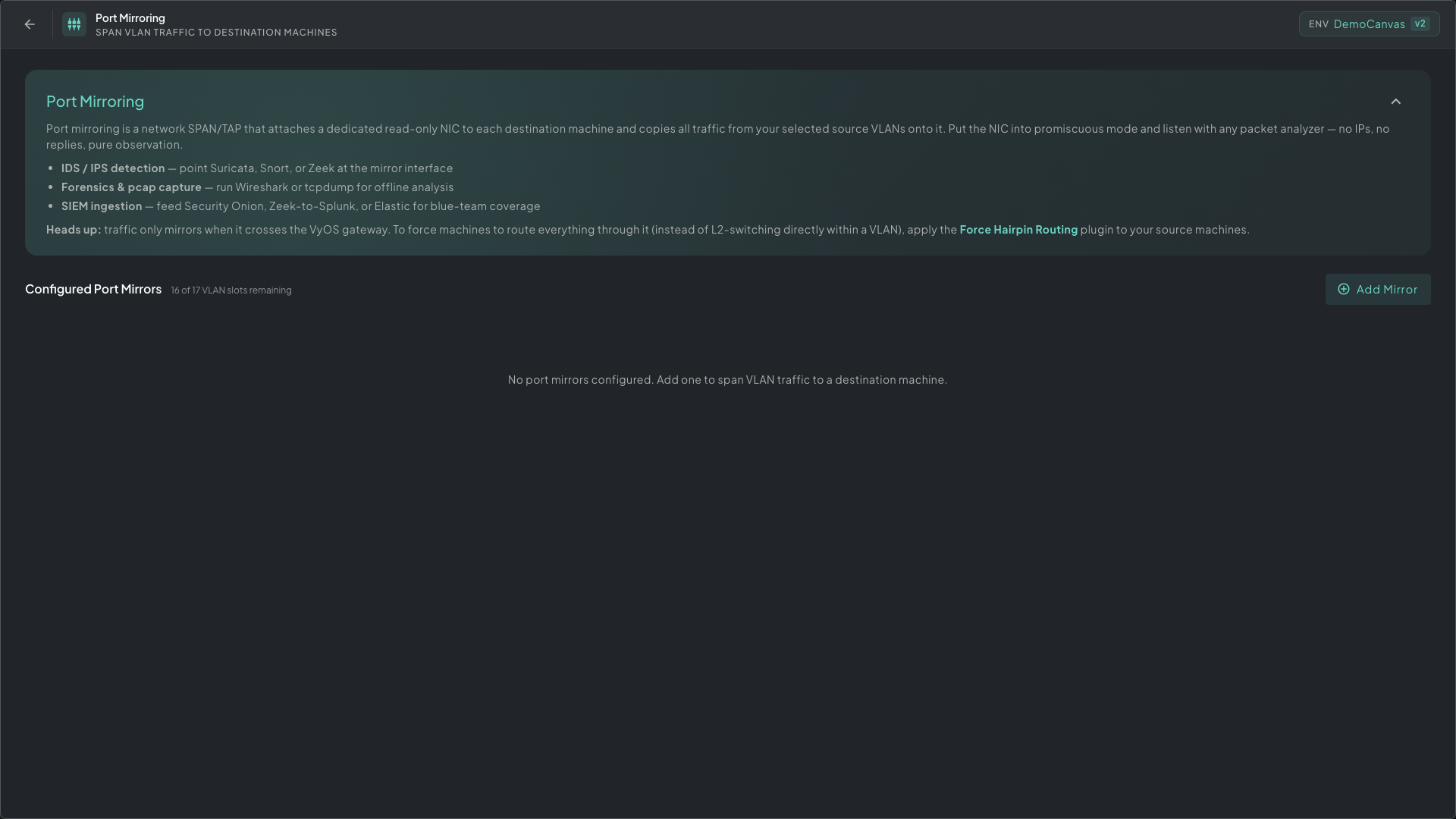 The Port Mirroring panel. Each mirror card shows its source VLANs and destination machines.
Each mirror uses one VLAN slot, like a regular VLAN. The panel shows how many slots are left. When they’re all in use, delete a VLAN or a mirror to add another.
Cloning
Section titled “Cloning”Right-click a VLAN to clone it. The clone includes all of the VLAN’s machines and their plugin configurations. This saves time when you need several similar network segments, for example one environment per team.